
Need measured shape?
Request a point-cloud or mesh package such as PLY, STL, or OBJ with the cleanup, coordinates, scale, and reference images agreed in scope.
A 3D scan usually begins as measured point-cloud or mesh data. Editable STEP or IGES geometry requires a separate CAD reconstruction scope. This guide helps buyers request the right deliverable before capture begins.
“A 3D file” can mean measured points, a triangle mesh, reconstructed CAD, a drawing, or a comparison image. The receiving software and downstream decision should be known before the deliverable is named.
Request a point-cloud or mesh package such as PLY, STL, or OBJ with the cleanup, coordinates, scale, and reference images agreed in scope.
Request separately reconstructed CAD in STEP, IGES, Parasolid, or an agreed native format. State the surfaces, features, interfaces, and editing needs that matter.
Request the geometry plus the drawings, deviation views, screenshots, or notes that the customer, designer, or vendor needs to interpret it correctly.
File extensions do not guarantee model quality, accuracy, editability, units, feature history, or fitness for manufacturing. Those requirements belong in the project scope.
Measured surface shape without feature history, reliable units, color, or texture. Useful for mesh reference, visualization, and many 3D-print workflows after suitability is reviewed.
Useful when a polygon mesh may need material or texture information and broad compatibility. The geometry is still a mesh, not reconstructed engineering CAD.
Useful for measured point, mesh, color, or other vertex data depending on the capture workflow and receiving software.
Useful for CAD exchange, editing, quoting, drawings, or downstream engineering review when a defined model has been reconstructed from the measured reference.
Still used in some surface and legacy CAD workflows. Confirm whether the receiving system prefers STEP, IGES, Parasolid, or a native model.
Useful for drawings, labeled screenshots, deviation maps, and review notes. These explain the geometry but do not replace the underlying mesh or CAD file.
The scan and reconstructed model may look similar in a screenshot, but they contain different information. The correct handoff depends on whether the recipient needs measured evidence, controlled CAD, or both.
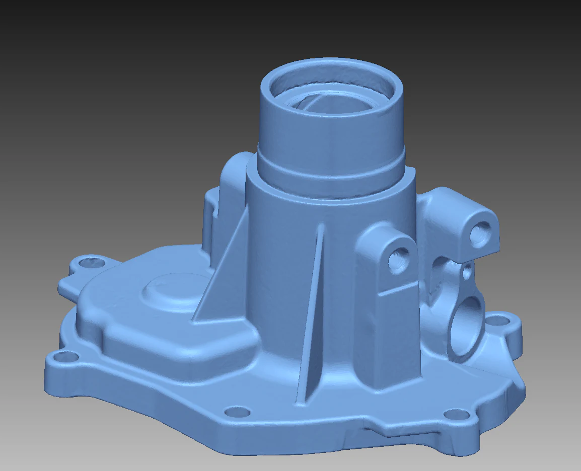 01 · Mesh reference
Point-cloud or polygon data records the captured condition, including visible wear, texture, noise, and incomplete regions.
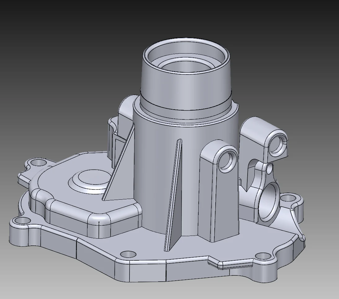 02 · CAD model
Surfaces, solids, holes, bosses, datums, and interfaces are rebuilt according to the agreed model class and intended use.
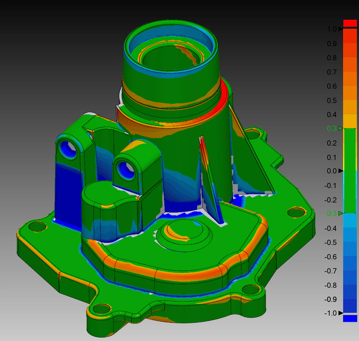 03 · Comparison
Deviation views can show how the measured condition and selected reference relate after alignment and display settings are defined.
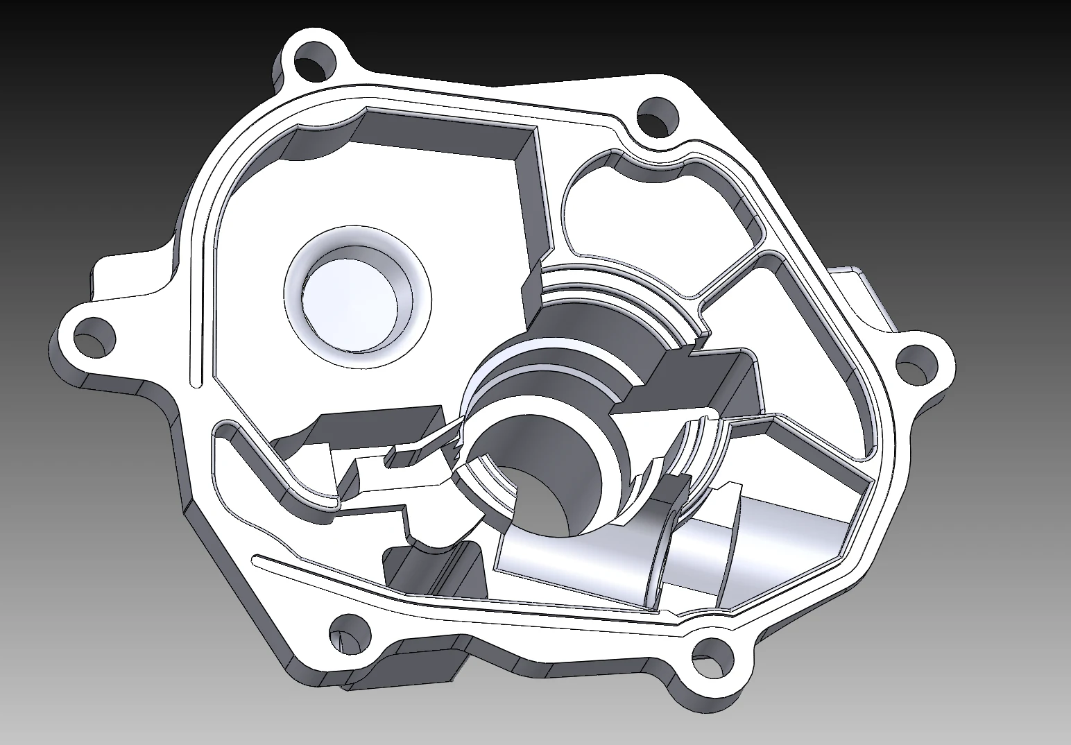 04 · Handoff detail
Neutral CAD, drawings, screenshots, and notes should be packaged around the software and decision awaiting the files.
The scanner records measured geometry that is aligned, cleaned, and prepared for the agreed purpose.
CAD is interpreted and rebuilt from the measured reference; it is not created by renaming or wrapping the scan file.
The fastest way to choose a format is to identify the receiving software, the required level of editability, and the decision the files must support.
STL represents surface shape with triangles and is commonly used for mesh delivery, visualization, reference, and 3D printing workflows. STEP stores CAD geometry such as surfaces or solids for exchange between CAD systems. A useful STEP model normally requires reconstruction from the scan rather than a simple export.
A scanner captures measured points that are processed into a point cloud or mesh. Some software can wrap or translate mesh geometry into a CAD container, but that is not the same as a controlled feature-based or surface-based reconstruction. The required editability and model class should be agreed before work starts.
OBJ is useful when mesh geometry may need companion material or texture information. PLY can preserve point, mesh, color, or other vertex attributes depending on the capture workflow. STL is a simpler triangle-only exchange. The receiving software and intended use should determine the choice.
STEP is a common neutral exchange format for CAD solids and surfaces. IGES is an older exchange format still used in some surface and legacy workflows. The recipient should confirm what its CAD or downstream system accepts; native feature history is a separate deliverable from either neutral format.
Describe what must happen next: archive the measured part, visualize it, 3D print it, edit features, quote manufacturing, compare it to reference CAD, or create drawings. Kymerion can then scope the measured mesh, CAD reconstruction, comparison material, and documentation package around that outcome.